Having a log splitter can save a lot of your time and effort. Having a homemade log splitter can also save you a lot of money. This article will thus offer you a detailed instruction on how to build a log splitter free plans.
When it comes to woodworking, a log splitter is one of the most fundamentals for your workpiece. And as there is a trend toward low cost yet still useful woodworking tools, DIY log splitters has been widely favored.
Even though building a homemade log splitter demands a lot of your energy and patience in creating, assembling and testing, the results is very rewarding. Having a log splitter made by yourself and using it for your wood furniture project is also a very enjoyable experience.
In this article, you will find the collected instructions on how to build a log splitter free plans. The recommended log splitter in this article is a hydraulic one, as it is one of the most commonly used log splitters and it is proven to be an excellent performer in chopping large woods.
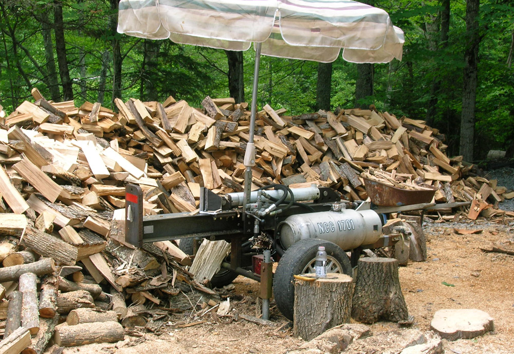
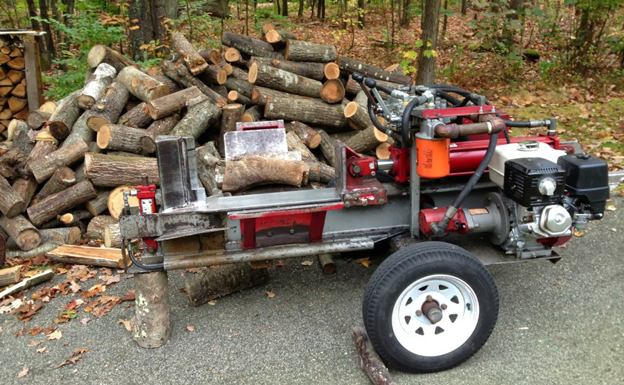
Description of the Hydraulic Splitter
This log splitter is designed with a 5 H.P engine and two-stage hydraulic pump (2.9 GPM at the high press and 10.6 GPM at the low press). It can split any logs with the diameter up to 18 inches.
About 15.7 tons of force is available using a hydraulic cylinder and increases up to 24 tons with the mechanical advantage (1.5 to 1) of a wedge.
The cycle time is approximately 10.5 seconds with full extend and retract no load.
The trailer coupler fit on 1 7/8” ball
An adjustable leg holds the splitter in place while the logs are cut
The automatic kick off valve allows both hands to be free to set up new log while the cylinder is retracting.
The operator has plenty of room to work with the log.
If you want to use a 24” stroke hydraulic cylinder, some parts will need to be changed. The length of the beam, the hydraulic hose, the location of the hydraulic tank and the kick off valve should be increased.

Bill of Material
For hydraulic cylinder
- One 4” bore, 18’” stroke or 24” stroke with 1’ pinholes or equivalent
For directional control valve
- One kick-off valve with relief valve (open center type)
- All hydraulic hoses ends are JIC #8 female except the suction hose
For frame assembly
- One trailer coupler fits on 2” ball
- One ¼” safety chain 14” long, one snap hook
- HSS 3/16 x 2 x 2 tongue (Square tubing)
- Two tires assy 4.8-4-8 (4 bolts, 4” center)
- Two spindles & hubs assy (stub axles)
- One W-beam ¼ x 6 x 6, 55” or 67” long
- One channel ¼ x 2 x 6 x 18
For hydraulic reservoir
- HSS 3/16 x 4 x 8 x 30
- One breather cap & 1 ½ O.D. x 3” long pipe
- 10 microns spin-on return line filter
For hydraulic pump & engine
- 5 HP Honda engine with 2.9 (high) and 10.6 (low) G.P.M, pump at 3600 RPM
- One pump mounting bracket & ¾” coupling, or buy a gas power packs assy
Note about welding
Always start with a temporary weld, try if the assembly moves free with the pins or bolts of if they are straight, take the time to do more measurements if needed then weld the parts together.
How to Build a Log Splitter Free Plans
Step 1: Hydraulic tank assembly
Drill 5 holes for the suction fitting, drain plug, pipe, microns oil filter assy and the locknuts. Clean the inside of the square tubing and remove all the metal flake.
Now as you are done with cleaning, test the tank, plug every hole, fill with water then pressurize the tank with 5 psi for about 2 minutes.
If there is no leak, empty the tank and blow the inside with air. Then, weld both hubs and spindles under the tank, keep the tire at about ¾” from the tank.
Finish the hydraulic tank assembly by installing 2 safety jacks under the tank to hold it in place then installing all fittings, vent, and hydraulic filter.
Step 2: Engine and hydraulic pump assembly
Install the engine in place with bolts and nuts but without the rubber pads. After the engine is set in place, weld the bolts in the 1.0” square tubing then remove the engine, let the bolts cool then install the rubber pads and reinstall the engine with the hydraulic pump and suction hoses.
Step 3: Beam assembly
Assemble the W-beam and then weld the cylinder bracket, kick of valve bracket, channel, adapter plate, spacer and hidden plates.
The position of welding depends on the length of the beam to use. After you are done welding the tongue, weld the chain retainer, chain, snap hook and trailer coupler. Then, weld the plate and round tubing together and bolt them in place.
Now you can install the beam assembly on the hydraulic tank using 4 spacers, bolts and locknuts, remove the safety jacks and install the hitch pin to hold the leg in place.
Step 4: Wedge and hydraulic cylinder assembly
Install the hydraulic cylinder on the beam with the pin and locks. Make the base cylinder plate, bottom plates and guide plates and bolt them on the beam.
Note that some shims may be required between the base plate and the guide plates. Also, the base plate should not move freely on the beam just by hand.
Next, weld the cylinder bracket on the base plate and weld the ½” plate flush with the cylinder bracket. Finally, weld the other plates to make the wedge.
Step 5: Hydraulic system
Install the kickoff valve, all hydraulic hoses, oil filter and fittings. Fill up the hydraulic tank with hydraulic fluid up to the level indicator glass.
Start the engine, let it run at idle and pull the lever to extend the cylinder completely then react the cylinder and shut the engine off. Refill the hydraulic tank at the proper level. Install a tee and hydraulic gauge on the cylinder extending port.
Restart the engine and let it run at high idle for about 5 minutes, extend the cylinder then set the relief valve on the kick off valve at 2000 psi while holding the cylinder in the full extending position. Now you can restart the cylinder with the automatic kick off valve.
Later on, you may have to reset the pressure at 2500 psi if more force is required. Now you hydraulic log splitter is done, and you are ready to paint the unit.
Some Thoughts about The Design
The most exhausting part of chopping wood with a standard log splitter is lifting the heavy log into the right position. Instead, a log splitter with cylinder moves vertically to slice logs on the ground will save a lot more time and energy.
Thus, whenever you want to process the wood, simply roll the logs up to the splitter and let them stand on the ground. Then, after they are halved, move each hunk back under the wedge to keep dividing them.
The foot pedal assembly can also be added to operate the machine and free your hands from positioning the wood and throwing split lengths to a nearby pile.
The pedal is attached to a spring that pulls the control lever into “Up” position when you take the foot off the control. This design will help you to walk away from the splitter or roll the log in place while the 27-inch-long cylinder is still rising.
It automatically shuts off when the top attached to the wedge hits the end of the valve and turns it back to the balanced position.
To transfer the log topper into the woods, you should mount the hydraulic system on a good old automobile axle which is towed by a V-shaped framework.
The 5” x 10” steel I-beam attached to the cylinder, and the wedge will then be fastened to bracket mounted on the axle. Eventually, it can be pivoted downward to the ride on top of the middle bar of the towing apparatus.
The vertical hydraulic log splitter provides you with ease of operation and transferring the logs. This splitter is truly an efficient tool for chopping wood. To have a look at the plan of this splitter, please consult the slides here.
Tips for Choosing the Parts
- Double-acting cylinder with more than 4” in diameter
- At least 5 HP engine
- Sharp and wide wedge
- Pressure relief valves to prevent damage
- Steel water pipe for hydraulic line is not recommended
- Clean hydraulic oil or non-detergent motor oil
- Positive displacement hydraulic pump or vane pump
- Secured cylinder (at both ends)
- Properly vented tank
- Smooth wedge that can ride snugly enough on the I-beam
- Suction line is larger in diameter than pressure line
- High-pressure housing return line is not necessary
Hopefully, with this instruction on how to build a log splitter free plans, you can make a log splitter by your own. Even though it can be an exhausting activity, what you are rewarded after it’s done is pretty amazing.
The best part is, you don’t need luxurious tools to chop the woods, a homemade log splitter can not only save a lot of your money in the long run but also make your woodworking easier. Make one and let it inspire.


